The performance
advantages promised by asynchronous circuits have
recently renewed interest in the development of related
CAD flows, particularly using commercial synchronous CAD
tools. This project applies synchronous logic synthesis
tools to produce multi-level domino asynchronous
pipelines using a two-step translation procedure.
Initially, standard logic synthesis tools are applied to
a standard RTL specification using a special image
library consisting of single-rail combinational gates
with timing arcs corresponding to domino dual-rail
equivalents. Then, the single-rail netlist is translated
into a dual-rail multi-level domino circuit by expanding
each single-rail gate into its dual-rail equivalent, and
adding pipeline control. This project also involves
running through several large examples, analyzing the
results, and identifying areas of future improvement.
Goal
Archieve the
low-latency benefits of asynchronous dual-rail pipelines
in a standard synchronous ASIC flow.
Current
Synchronous ASIC Designs VS. Proposed Future ASIC
Designs
(a) A
Classic synchronous circuit
(b) A
proposed Future ASIC circuit
In a
classic synchronous circuit, combinational static logic
is bounded by flip-flops driven with clock-trees as
shown in figure (a). The clock speed must be defined for
the worst-case delay from flip-flop to flip-flop,
considering process variations, IR-drop, and cross-talk.
In contrast, the asynchronous circuit spans multiple
flip-flops, enabling implicit perfect clock borrowing
across multi-cycle paths and useful skew. Moreover,
lower power for the same performance may be achieved as
large portions of clock-tree are eliminated. In figure
(b), the boundaries between asynchronous and synchronous
designs are implemented with special
synchronous-to-asynchronous (S2A) and
asynchronous-to-synchronous (A2S) flip-flops. S2A
transforms synchronous wires to asynchronous protocol
using the global clock as reference to toggle the data
lines. Similarly, A2S converts dual-rail wires back into
single-rail representation, and it also produces error
signals if asynchronous logic is not valid sufficiently
before clock arrives. There may also be multiple
asynchronous islands within the overall design,
typically used where performance is critical.
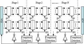
Multi-level Domino Asynchronous Pipelines
The completion detection
comprised of a pre-charged logical AND tree shown in
figure 6 is used for signal validity and neutrality
between pipeline stages. The output of the completion
detection in the stage N acts as an enable signal (go)
for the stage N-1 through an inverter. During dual-rail
conversion, each gate is converted to dual-rail gates
(DR) when driving gates are in the same stage while it
is converted to dual-rail gates with an additional
completion port for detecting output changes (DR_NAND)
when driving gates are in the different stage. Assuming
the number of levels of logic per pipeline stage is 2 as
shown in the above figure, the second gates on each
stage are DR_NAND gates, and the change of the output of
DR_NAND gates is detected in ‘Completion Detection’
(CD).
This pipeline style is
similar to the PSO design with a pre-charged completion
detection unit.
Proposed
Synthesis Flow
The
starting place of our RTL design flow is the same as
synchronous design flow as shown in the above figure.
The input of this flow is the RTL VHDL or Verilog.
During the partitioning step, the asynchronous islands
must be identified. Using a standard cell library, a
commercial synthesis tool performs HDL optimizations
during classic logic synthesis using Cadence RTL
Compiler. In order to translate synchronous into
asynchronous circuits, slack matching and dual-rail
conversion is performed. In the first step, optimal
levelization is performed to ensure that there will be
no pipeline stages that have thru-wires that would cause
malfunction, by adding a minimum number of buffers to
the design. In the second step, the single-rail netlist
is converted into a dual-rail multi-level domino circuit
by replacing each single-rail gate with its dual-rail
equivalent and associated pipeline control circuitry is
added.
To support the synthesis
procedure, we designed a dual-rail library of gates and
create a single-rail image for each gate that we put
into a synchronous image library. To create an image of
a cell, we map the dual-rail timing arcs to their
synchronous equivalent, taking the maximum of multiple
dual-rail arcs where necessary.
Experimental
Results
The
following table illustrates the pre-layout results from
RTL Compiler, where column latency and area numbers are
the improvement rate normalized by the result of
synchronous circuit with a commercial synchronous
library, the asynchronous image library, and the
asynchronous dual-rail library all using TSMC 0.13μ
technology parameters.
The results demonstrate
that our new design flow can achieve an average logic
delay latency reduction of 36% for the nominal process
point.
Future
Works
Publications
Logic Synthesis of
Multi-level Domino Asynchronous Pipelines, N. Kim, P. A.
Beerel, A. Lines, A. Kondratyev, and K. Lwin, 42th
Design Automation Conference, submitted, June 2005.
Acknowledgements
Please contact me at
namhoonk@usc.edu
if you have any sugestions or questions.